Features · Survey & design
Design on the real floor plan — in 2D and full 3D.
Upload the drawing, anchor it to the site, and place every discipline from a product library that carries the manufacturer's specs. The canvas is fast; the model behind it is the one every physics engine reads.
The working canvas
- Layers
- cameras · Wi-Fi · access control · cabling · racking · A/V · zones
- Floors
- per-floor plans, one building model
- Background
- Auto · Original · Cleaned · Faded · Vector
- Scale
- GPS-anchored — feet on screen are feet on site
One canvas, every discipline — 2D for speed, 3D for truth.
What you place
Every discipline, one canvas
Devices come from a real product library, land in a shared obstacle model, and render in 2D and 3D from the moment they are placed.
Cameras
Placement with real lens physics: field-of-view cones that respect walls, glass, and racking, with a per-camera 3D point-of-view.
Wireless
Access points with datasheet-derived vendor antenna patterns and per-zone RF parameters — coverage that reads the building, not a circle around a dot.
Access control
Readers paired to controllers with real cable runs — distances from the plan scale, service loops, and protocol-correct cable types.
Cabling & risers
Cable paths drawn on the plan with computed lengths, riser runs between floors, and drops that land in the bill of materials.
Racking
Warehouse racking as areas or drawn runs — laid out, rendered in 3D, and treated as structure by every physics engine.
Conference A/V
Displays, speakers, microphones, and video bars — placed on the plan and scored seat by seat by the A/V engine.
Furniture & elements
Doors, windows, glass walls, desks, industrial fans — an elements library that doubles as the obstacle model.
Zones & ceilings
Zone polygons carry per-space parameters, and ceilings render as six real types — from 2×4 drop grid to warehouse bar joist.
From paper to model
Start from the drawing you actually have
Real projects start from scans, exports, and photographs of drawings taped to a wall. The studio takes what you have, anchors it to the real world, and turns it into a model — without making the drawing's quality your problem.
- Upload plan images or PDFs and set real-world scale by anchoring the plan to the site — GPS anchoring keeps every distance honest.
- SOC traces walls and suggests materials; you confirm before anything computes. Wall material and thickness carry straight into the physics.
- Messy or missing drawing? The adaptive basemap draws the plan from the model itself — with original, cleaned, faded, or pure-vector backgrounds.
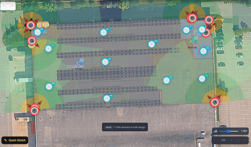
Background modes
- Auto
- picks the best available basemap
- Original
- the drawing exactly as uploaded
- Cleaned
- text and clutter lifted from the plan
- Faded
- the plan recedes, the design leads
- Vector
- drawn from the model — no raster needed
The design never depends on the quality of the scan.
One model
Floors, zones, walls, and ceilings that mean something
Everything you place lands in one obstacle model — the same geometry the physics engines read. The building is not a backdrop; it is an input.
- Multi-floor buildings with per-floor plans and designs — one model, not one file per floor.
- Zones carry per-space parameters: an office and a warehouse aisle compute differently because they are different.
- Six ceiling types render in 2D and 3D — drop grid, open plenum, coffered, bar joist, high bay — and pair with materials the engines respect.
The obstacle model
- Walls
- real materials and thickness, drawn or detected
- Glass
- doors, windows, glass walls — own RF attenuation; windows see-through for cameras
- Racking
- areas and runs, structural to every engine
- Ceilings
- six types, visual and material
- Furniture
- the elements library doubles as obstacles
One geometry. Every engine reads it.
Real products
A product library that carries the datasheet
Devices here are not icons — they are products, with the manufacturer's specifications attached and consumed by the math.
- Lens and sensor specs, antenna patterns, IR range, speaker output, PoE draw — on the product, feeding the physics.
- SOC researches and enriches product data from your documents and the vendor's published specs — as suggestions with provenance, never silent edits.
- Place a product once and the physics, the bill of materials, and the reports all describe the same device.
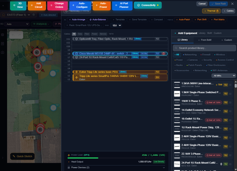
One product, everywhere
- Physics
- FOV, RF, and audio from its datasheet
- BOM
- the line item, its accessories, its licensing
- Reports
- schedules, site plans, as-builts
- Portal
- what the customer sees delivered
Two views, one truth
From canvas to full 3D
The same model extrudes into a walkable building — walls at their real heights, doors that open, glass that reads as glass, ceilings and racking as placed.
- Orbit the building or walk it in first or third person — the 3D is the model, not an artist's impression.
- Ceilings, racking, furniture, and devices render exactly as placed on the canvas.
- In the walkthrough, every discipline reports live numbers at your position — that story is the platform's.
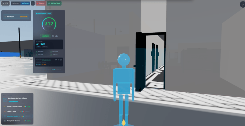
What extrudes automatically
- Walls
- real heights, real materials
- Doors & glass
- openings that behave like openings
- Ceilings
- procedural, per zone type
- Racking & furniture
- as placed, at scale
- Devices
- mounted where you put them
No export step. No second model.
Deliverables
The paper it produces
Everything below derives from the same model — change the design and the documents follow.
Site plan sets
Print-ready ARCH-D sheet sets: per-discipline layers, schedules, title blocks, and cross-sheet references.
Floor plan reports
Per-discipline pages with friendly and TIA-606 labeling on devices, drops, and cable paths.
Design proposals
A customer-facing document built from the same model — coverage, gear, and scope in one narrative.
Map image exports
Clean, labeled plan images for emails, tickets, and RFPs — with the background mode you choose.
Frequently asked questions
What file types can I start from?
Floor plan images and PDFs. Set the real-world scale by anchoring the plan to the site, and the model keeps every distance honest from there. If the drawing is poor — or missing — the adaptive basemap can draw the plan from the model itself.
Do I have to trace every wall by hand?
No. SOC detects walls and suggests materials, and you confirm or correct them before anything computes. Materials are not cosmetic: a glass wall and a concrete wall attenuate Wi-Fi very differently, and windows let cameras see through where solid walls do not — so the model records what each surface actually is.
Is the 3D view a separate model I have to maintain?
No. The 2D canvas and the 3D building are the same model. Place a camera on the plan and it is standing there in 3D with the same product specs and the same physics — nothing is exported, converted, or redrawn.
Can several disciplines share one design?
Yes — that is the point. Cameras, Wi-Fi, access control, cabling, racking, and A/V live in one model with per-discipline layers, so a change to the building updates every discipline at once.
Design your next site on the real plan
Upload a floor plan, place a few devices, and watch the physics respond. Talk to us about what your team needs.