Features · Network design
The model that computes coverage designs the network.
The same building model that places your cameras and access points already knows every drop, distance, wall, and closet. So the topology, the racks, the cabling, and the pull plan derive from it — instead of being drawn again in a diagram tool that never learns the building.
From model to network
- 01 Drops every placed device is an endpoint
- 02 Closets MDF and IDFs on the actual floor plan
- 03 Topology five tiers assembled from the design
- 04 Racks elevations in BICSI order, in 3D
- 05 Cabling schedules and labels, export-ready
- 06 Routing pathways solved with pull physics
One source. Every layer derived.
Topology · Port & patch planning
A tiered topology, generated — not drawn
From the placed devices, the closets, and the cable paths between them, the platform assembles the network as a graph — and plans the ports to serve it.
- Five tiers — WAN, perimeter, core, distribution, access — built from what is actually in the design, with per-closet layouts, device groups, and switch summaries.
- Switch-port and patch-panel planning per closet: port assignments, suggested VLAN groupings by device class, and PoE budgets read from the placed loads.
- Patch routing follows structured-cabling practice — device to patch panel, panel to switch — tracking both sides of every patch-panel port so nothing is double-booked.
- Deterministic derivation: the same design produces the same plan, every run.
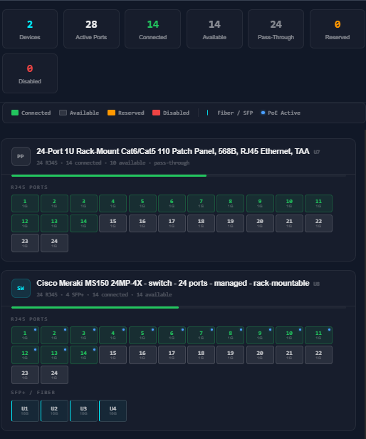
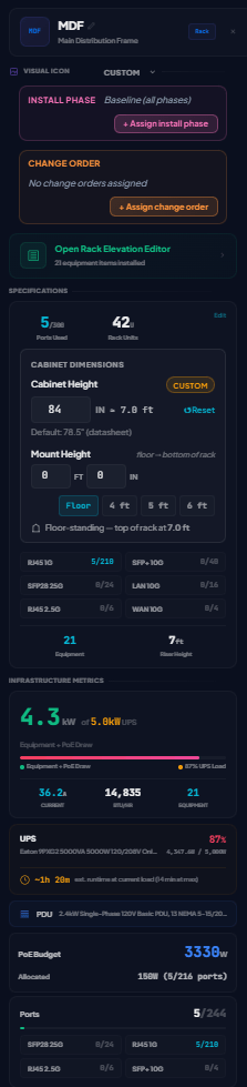
The access layer, planned
- Ports
- every device assigned, per closet
- VLANs
- suggested groupings by device class
- PoE
- budgets from the placed loads
- Patching
- device → panel → switch, both sides tracked
Planned from the design — you approve, it documents.
Racks & MDF/IDF · BICSI
Rack elevations that follow the conventions
Cabinet layout is opinionated the way a BICSI-trained designer is opinionated: weight low, distribution logical, patching where hands can reach it.
- Rack elevations ordered to BICSI placement conventions — UPS and heavy equipment at the bottom, core and firewall lower-mid, distribution above, patch panels and cable management at the top.
- Every placement suggestion carries its reasoning and the standard reference it follows — review it, accept it, or overrule it.
- Blanking panels suggested for empty gaps, and cable management sized to the switching it serves.
- The MDF and each IDF render as 3D cabinet models in the same scene as the rest of the design — the closet is part of the building, not a separate drawing.
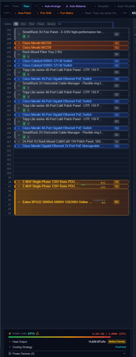
A rack, ordered
- 01 Bottom UPS and the heaviest equipment
- 02 Lower-mid core switching and firewall
- 03 Mid distribution and PDUs
- 04 Upper access switching
- 05 Top patch panels and cable management
BICSI placement conventions, applied and cited.
Structured cabling · BICSI / ANSI-TIA
Cable schedules and labels, emitted from the plan
Copper and fiber are planned on the real plan scale, validated against the standards, and documented in the formats installers and inspectors expect.
- Copper Cat5e through Cat8 and fiber OM1–OM5 / OS1–OS2, with run distances validated against ANSI/TIA-568 limits and BICSI TDMM practice.
- Fiber trunks allocated strand by strand — duplex links or MPO groups of 12 and 24 — with TIA-598 color coding applied automatically.
- Per-closet cable schedules with cable types, ratings, PoE classes, and device and closet labels — ready for the design proposal and the field.
- Labels follow TIA-606-D administration formats, with termination color coding carried through to the documentation.
One drop, documented
- Cable
- type and rating, plenum or riser
- Distance
- validated against TIA-568 limits
- Label
- TIA-606-D administration format
- Color
- TIA-598 strands, termination coding
- Ports
- panel rear, panel front, switch
Cable-path optimizer
Routing solved as an optimization, not a guess
Which closet serves which drop, through which pathway, at what conduit size — that is an optimization problem, and the platform solves it as one.
- An integer linear program assigns every endpoint to a closet and pathway, minimizing cable length, pathway sizing cost, and zone penalties — solved deterministically with branch-and-bound.
- Closet capacity, conduit and tray fill, and spare-capacity headroom are hard constraints, not afterthoughts.
- Pull tension is modeled with the standard pulling equations — including the capstan effect on every bend — and runs split with pull points where tension, bend accumulation, or length exceeds limits.
- Routes that cannot be pulled are pruned before the solver ever considers them.
Pull feasibility
- 01 Straight run tension grows with length, weight, friction
- 02 Around a bend multiplied by e^(μθ) — the capstan equation
- 03 Over the limit a pull point splits the run
- 04 Result a route the crew can actually install
Physics decides the route before anyone pulls cable.
What derived network design buys you
- 5 tiers
- WAN to access
- The topology assembles from the placed design — not a stencil library
- ILP
- Routing as optimization
- Length, pathway fill, and spare capacity solved as real constraints
- TIA-606-D
- Labels and colors
- Administration-standard formats emitted with the schedules
- One model
- Drops to pull plan
- Change the design and re-derive — nothing is redrawn by hand
Frequently asked questions
Do I have to draw the topology myself?
No. The topology derives from the design — the devices you placed, the closets they home to, and the cable paths between them — as a pure computation. Move a camera to a different closet or add an IDF, and the tiers, port plans, and schedules re-derive from the model instead of waiting for someone to redraw a diagram.
Is this tied to a switch vendor?
The plan is vendor-neutral. Port assignments, suggested VLAN groupings, PoE budgets, and labels are computed from the devices and products in your own library — the design decides the requirements, and you choose the hardware that meets them.
What does the cable optimizer actually optimize?
It solves an integer linear program: every drop is assigned to a closet and a pathway so that total cable length, pathway sizing cost, and zone penalties are minimized — subject to closet capacity, conduit and tray fill, and spare-capacity headroom as hard constraints. Routes that would fail the pull — too much tension, too many bends, too long — are pruned before the solver considers them. The same design produces the same answer every run.
Does it configure my switches?
No — this page is design-time planning: what to buy, where it lands, how it patches, and what to label it. For the running network, NetCommand compares the designed state against what is observed and returns prioritized, advise-only remediation. It never pushes configuration.
Design the network from the building, not a whiteboard
Place the devices once — the topology, racks, schedules, and pull plan follow. Talk to us about what your team needs.