Features · Power & electrical
The model that places your devices budgets your power.
Every camera, access point, and switch on the plan carries its watts — so PoE budgets, branch circuits, UPS runtime, heat load, and phase balance are computed from the design itself, with the NEC article or IEEE standard named on the advice.
The standards on the plan
- IEEE 802.3 af/at/bt
- PoE classes, to 71 W per device
- NEC 2023
- Art. 210 · 215 · 220 · 240 · 408
- IEEE 1584-2018 · NFPA 70E
- arc-flash screening and PPE
- IEEE 485
- battery and runtime sizing
- IEEE 141 · NEMA MG-1
- fault and phase-balance limits
- ASHRAE TC 9.9
- thermal envelopes and airflow
Cited on the advice itself — every recommendation names its source.
PoE budgets
Every device carries its watts
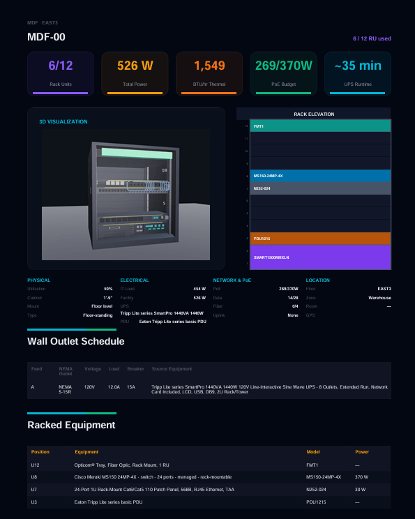
Place a camera and the closet feels it. PoE budgets assemble from the design — device power specs, cable-path assignments, switch capacity — instead of a spreadsheet somebody keeps almost up to date.
- Devices classify against all four IEEE 802.3 PoE classes — af, at, and bt Types 3 and 4 — up to 71 W delivered per device.
- Budgets assemble per closet from the cable paths: maximum and typical draw, checked against the switch's PoE capacity.
- Switch recommendations carry a 20% power and 25% port headroom rule, and short budgets are flagged before install.
- Live where you work: the closet details panel budgets PoE as you place devices, and the proposal prints the budget table with utilization status.
One closet, budgeted
- Class
- af · at · bt Type 3 · bt Type 4
- Draw
- maximum and typical watts per device
- Budget
- demand vs switch PoE capacity
- Headroom
- 20% power, 25% ports in reserve
- Warning
- flagged before anyone installs
Assembled from cable-path assignments — not typed into a spreadsheet.
Circuits & voltage drop
Branch circuits, sized the way the NEC reads
Circuit allocation is a bin-packing engine with the NEC arithmetic applied — and it is deliberately advisory. It flags what needs an electrical engineer; it never replaces one.
- Breakers size per NEC 2023 — 125% of continuous load per Art. 210.20(A) and 215.3, the next standard rating per 240.6(A), 80% usable capacity.
- Dual-corded equipment keeps its A and B feeds on separate circuits, and every connector validates against real NEMA and IEC 60320 tables — plug, receptacle, ampacity, voltage.
- Panel schedules generate with A-B-C phase rotation and spare-slot tracking, and the circuit set prices itself as bill-of-materials deltas — breakers, receptacles, whips, panelboards.
- Voltage drop screens against NEC guidance — 3% branch, 5% total — with single- and three-phase formulas chosen by breaker pole count, and notes that name the offending device and suggest conductor upsizing.
One circuit, checked
- 01 Load continuous × 1.25, per Art. 210.20(A)
- 02 Breaker next standard rating, per 240.6(A)
- 03 Capacity 80% usable, spare slots tracked
- 04 Connector NEMA and IEC 60320, validated
- 05 Drop 3% branch, 5% total screening
Advisory by design — an engineer signs the final word.
Arc flash & fault
Screening the hazard before anyone opens a panel
Arc-flash awareness belongs at design time, not discovery time. The platform screens incident energy with the IEEE 1584-2018 simplified method — and is explicit that screening is what it is.
- Incident energy estimated in cal/cm² per the IEEE 1584-2018 simplified method, with electrode configurations from the standard's own tables.
- The arc-flash boundary computes at the 1.2 cal/cm² threshold, and PPE categories 0 through 4 assign per NFPA 70E (2024) Table 130.5(G).
- Warning-label text generates with working distance, boundary, and required PPE spelled out.
- Short-circuit estimation per IEEE 141 feeds the same electrical kernel, so fault levels and arc energy stay consistent with each other.
- Screening, not a study — the result says so, and the engineering stays with a licensed engineer.
The label, spelled out
- Energy
- cal/cm² at the working distance
- Boundary
- where 1.2 cal/cm² lands
- PPE
- category 0–4, per NFPA 70E
- Config
- VCB · VCBB · HCB electrode setups
- Fault
- short circuit per IEEE 141
Estimates for planning — an arc-flash study belongs to a licensed engineer.
UPS & runtime
Runtime you can defend in the proposal
Most tools print the brochure runtime. This one sizes the UPS from the actual protected load, estimates runtime the conservative way, and labels the number for what it is.
- UPS sizing from the load itself: watts to volt-amps with power factor and headroom applied, rounded to standard UPS sizes.
- Battery amp-hours follow the IEEE 485 method, and runtime estimates interpolate vendor datasheet curves scaled by Peukert's law — so light loads don't inflate the promise.
- Dual-path aware: single- and dual-corded loads split across A and B sides, and in 2N failover each side must carry the full load alone.
- Redundancy analysis maps N, N+1, 2N, and 2N+1 against availability tiers per BICSI 002 and TIA-942 — and lists the single points of failure.
- The cabinet report publishes the conservative full-load figure and labels runtime a planning estimate — real runtime depends on the battery configuration, and the deliverable says so.
One UPS, sized
- 01 Load watts on the protected side
- 02 Size VA with power factor, plus headroom
- 03 Batteries amp-hours per IEEE 485
- 04 Runtime Peukert-scaled, checked against target
- 05 Failover 2N sides each carry the full load
Printed as a planning estimate — the honest number, not the brochure number.
Heat & airflow
Watts become BTU before they become a problem
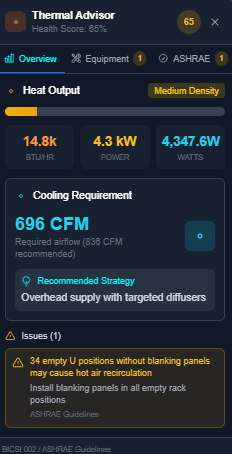
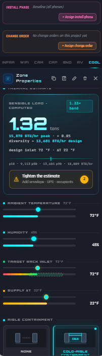
Every powered device on the plan is also a heater. The model totals the heat per rack and per room, computes the airflow to remove it, and checks the aisles actually move it the right way.
- Heat load converts at 3.412 BTU per hour per watt — per device, per rack, per room — with cooling tons where the room rolls up.
- Airflow needs compute in CFM from the design temperature delta, with air density corrected for site altitude.
- Hot/cold-aisle compliance checks every intake and exhaust direction, and blanking-panel gaps are flagged per empty rack unit.
- Density escalates honestly: racks past 20 kW get pointed at in-row, rear-door, or liquid cooling options.
- Thermal envelopes check against ASHRAE classes — recommended and allowable ranges for temperature, humidity, and dew point.
One rack, thermally
- BTU
- 3.412 × watts, summed per rack
- CFM
- from the ΔT, altitude-corrected
- Aisles
- intake cold, exhaust hot — checked
- Gaps
- blanking panels per empty U
- Density
- past 20 kW, liquid options surface
ASHRAE TC 9.9 envelopes, checked at design time.
Three-phase & panelboards
Balance computed with phasors, not rules of thumb
Three-phase loading is complex arithmetic — literally. The engine computes line currents from complex phasor math, and a panelboard optimizer keeps cost, balance, and headroom in one objective.
- Line currents come from true complex phasor arithmetic — delta branch to line — per IEEE 141, not a √3 lookup.
- Imbalance measures max minus min over average, against NEMA MG-1 thresholds: monitor past 5%, derate motors past 10%.
- The panelboard and feeder optimizer assigns loads, sizes breakers to NEC Articles 210, 215, 220, and 408, and rebalances phases by local search — minimizing cost, imbalance, and lost headroom together.
- Voltage, path, and short-circuit (SCCR) compatibility gate every assignment, and feeder ampacity checks at 125% of continuous load per Art. 215.2(A)(1).
- Deterministic and golden-tested — the same design solves to the same panel schedule.
One panel, balanced
- 01 Assign loads to slots, A-B-C rotation
- 02 Size breakers to the NEC arithmetic
- 03 Balance phases rebalanced by local search
- 04 Gate voltage, path, SCCR compatibility
- 05 Verify feeders at 125% continuous
Seeded solver, golden tests — reproducible to the digit.
The advice cites the code.
Power recommendations name their source — NEC 210.20(A) on the breaker, IEEE 1584-2018 on the label, NEMA MG-1 on the imbalance. SOC never invents the numbers: the deterministic engines own every figure, and where a licensed engineer must sign, the platform says so instead of pretending.
The trust architecture, on the platform pageDownstream
Where the power design lands
The same model that budgets the power fills the documents — nothing is re-keyed between tools.
Electrical requirements, exported
Outlet counts, AC watts, PoE watts, and BTU per hour with NEC compliance badges — in the proposal, the survey report, and the permit package.
Cabinet infrastructure report
Per-closet power, UPS runtime at conservative full load, and heat — the planning numbers behind every cabinet, labeled as planning numbers.
Fire-alarm battery calcs
NFPA 72 secondary-power sizing and notification-circuit voltage drop on NEC Chapter 9 conductor tables — generated for permit submittals, licensed-professional disclaimer attached.
Bill of materials
Breakers, receptacles, whips, and panelboards come back as bill-of-materials deltas from the circuit set — priced with the rest of the design.
Frequently asked questions
Where do the watts come from?
From the design. Devices placed from the product library carry their power specs; PoE classes are read from the datasheet or inferred from maximum draw; and budgets assemble per closet from the cable-path assignments — nothing is re-keyed into a spreadsheet.
Does this replace an electrical engineer?
No, and it is built not to. The circuit and voltage-drop output is advisory screening with the NEC arithmetic applied; arc flash uses the IEEE 1584-2018 simplified method and says so; and permit deliverables carry a licensed-professional disclaimer. It flags what needs an engineer — it never replaces one.
How honest is the UPS runtime number?
It is labeled a planning estimate, because it is one. Runtime interpolates vendor datasheet curves and scales by Peukert's law for lead-acid batteries, and the cabinet report publishes the conservative full-load figure. Real runtime depends on the battery configuration, and the deliverable says exactly that.
What does the arc-flash screening produce?
Incident energy in calories per square centimeter at the working distance, the arc-flash boundary, a PPE category from 0 to 4 per NFPA 70E, and generated warning-label text. It is screening for planning — an arc-flash study remains an engineering deliverable.
Can it balance a three-phase panel?
Yes — with phasor arithmetic, not a rule of thumb. Line currents compute from complex math per IEEE 141, imbalance is measured against NEMA MG-1 thresholds, and the panelboard optimizer rebalances phases while sizing breakers and feeders to the NEC.
Is the heat math per rack or per room?
Both. Every powered device converts to BTU per hour, totals roll up per rack and per room with cooling tons, airflow computes in CFM with altitude-corrected air density, and hot/cold-aisle direction and blanking-panel gaps are checked per rack unit.
Budget the power on the same model as the coverage
Bring a floor plan — the watts, circuits, runtime, and heat come from the design itself. Talk to us about what your team runs.